


close
Choose Your Site
Global
Social Media
Views: 0 Author: Site Editor Publish Time: 2026-10-30 Origin: Site


Select a beam adapter by matching its documented grip to the actual steel flange, its attachment point to the mating brace, and its permitted load case to the force at that connection. A clamp that fits over the edge is only a starting point: seating, position, direction and the capacity of the supporting steel also need to match the proposed installation.
For a dependable selection, measure the flange at the intended grip, sketch the adapter position and load direction, then request the exact model’s drawing, installation instructions and applicable load table. Do not substitute the rating of a similar-looking beam clamp.
Measure flange thickness at the actual contact point, not just the nominal beam designation. Compare it with the selected adapter’s minimum and maximum permitted thickness. A tapered flange may be thicker at the intended grip than at the free edge; identify the profile and ask whether the adapter is approved for that surface.
Record the full flange width and the distance from its free edge to the web or nearby obstruction. Width matters for an adapter that spans the beam; an edge-gripping design may instead be controlled by the accessible edge, grip depth and clearance. Do not assume that a width range published for one design applies to another.
Contact area: Show the upper and lower flange surfaces, any slope, fillet near the web, welds, coatings or damage that could affect the specified seating.
Accessible space: Note obstructions on both sides of the flange and room for the clamp body, screw, wrench and mating connection.
A useful sketch: Label the beam section, measured thickness and width, proposed flange and edge, and units. Add a photograph if it makes the contact surfaces clearer.
A jaw that reaches around a flange but bears on a fillet or obstruction may not seat as intended. If the surfaces do not match the drawing, ask the manufacturer and project engineer whether an alternative connection is suitable.
Identify whether the adapter will engage the upper or lower flange, which free edge is accessible, and which way the clamp body and attachment point will face. “Top” and “bottom” can describe different things: the beam flange, the face of that flange, or the adapter’s own orientation. Mark all three on a sketch and compare them with the manufacturer’s installation drawing.
Contact: The contact surfaces and any set screw must land where the selected instructions require.
Access: Check that the body seats as shown and that the screw can be tightened and inspected without interference.
Installation details: The allowable edge position, screw arrangement and tightening method are model-specific; use the actual instructions rather than a generic torque or edge distance.
For example, an adapter may physically fit a lower flange but place its connection hole against a nearby obstruction. Moving it to the opposite edge may change the load orientation. Confirm the new position and force direction in the documentation before treating it as equivalent.
Separate the flange-clamping hardware from the hole or thread that accepts the brace connection. Record which feature is threaded, which is a clearance hole, the intended bolt or mating component, and the available room to assemble it. A hole designation alone does not establish thread pitch, bolt grade, engagement, or a compatible brace assembly.
MaitoLead lists a ductile-iron beam adapter and a carbon-steel beam adapter, with 1/2-inch or M12 structure bolt-hole options stated on their product pages. The listed hole options do not identify thread pitch or establish that hardware is interchangeable; confirm the exact drawing and supplied hardware for the selected variant. For either adapter, the flange grip range, mounting orientation, tightening requirements and direction-specific ratings need confirmation against the selected variant’s current manufacturer documents.
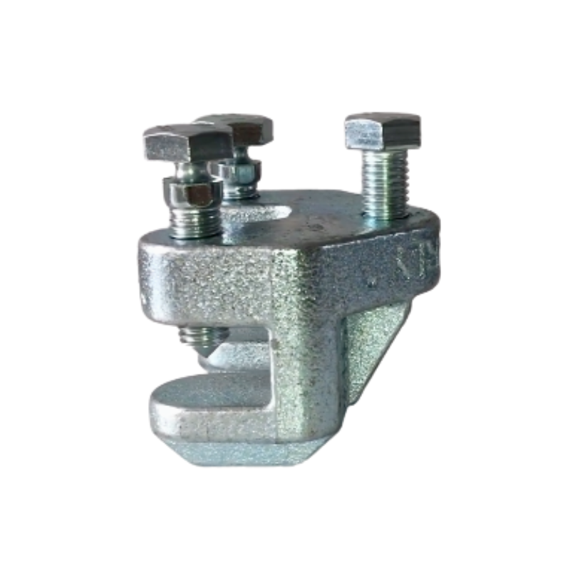
MaitoLead ductile-iron beam adapter: clamping opening and hardware shown for identification.
Check whether the mating component can align and move as the documented assembly requires without bearing against the beam or clamp body. Do not substitute bolts, washers or other parts unless the manufacturer permits the combination.
Show the force at the adapter, not just the direction of the pipe. On a sketch label the beam’s long axis, the direction across the beam, and up and down.
Force arrows: Draw the expected force arrows and identify their sense, magnitude and units for each relevant load case.
Direction reference: If a manufacturer uses “parallel” or “perpendicular,” establish whether the reference is the beam axis, flange surface or another datum.
Brace angle: Show the brace angle and the line from which it is measured. An angle measured from vertical is not necessarily the same as one measured from the flange; identify the reference in the applicable drawing.
A stated vertical hanging capacity cannot automatically be used for a side pull, uplift or an angled brace load; use the rating and configuration identified for that case. If loads act together or reverse direction, ask the manufacturer how the complete load case is evaluated; do not combine separate directional ratings without an approved method.
A manufacturer’s diagrams may distinguish the orientation of the steel flange, the direction of force and the brace angle. Use the diagram and notes supplied for the selected adapter and mating assembly to identify the applicable case.
A useful load table identifies the complete configuration behind each value. Start with the exact part and revision, then match the beam and flange, mounting position, force direction, brace angle and mating connection to the table’s drawings and notes. Check that the demand and the published rating use compatible units and design basis; an allowable load and a factored resistance are not automatically comparable.
Inputs needed to select the applicable load case | |
Input | What to establish |
|---|---|
Adapter and hardware | Exact model, size or variant, document revision, mating parts and fasteners. |
Beam interface | Flange profile and measured thickness; width or grip geometry where relevant; upper/lower flange, edge, and orientation. |
Force and angle | Magnitude, units and sense for each required direction; brace angle and its reference line. |
Rating and conditions | Allowed load case, rating units and basis, installation and tightening requirements. If an approval is required, identify its issuer, standard and edition, covered model, components and installation. |
Supporting structure | Beam identity and connection location for the project engineer’s structural check. |
Consider a hypothetical lower flange with a flat profile and a measured thickness of 10 mm. The proposed brace uses a specified mating bolt and has a brace angle of 45 degrees from vertical and a horizontal force component across the beam. Suppose the selected adapter's instructions cover that flange profile, thickness, edge and hardware, and its load table has a row for this position, direction and angle. The project engineer can compare the force and rating on the applicable basis after confirming the complete configuration and table notes, and assess the assembly and beam. If the table covers only vertical hanging loads, it does not establish a rating for this across-beam case. These hypothetical conditions are not specifications for a MaitoLead product.
The adapter rating alone does not establish the capacity of the supporting steel or the complete assembly. Give the project engineer the applicable adapter documentation, beam details and connection loads so the complete connection can be assessed under the project’s design method.
Where an approval is required, verify the actual product, assembly and installation scope in current records of the issuing body.
Send the supplier the selected product or required function together with the details needed to identify the installation:
Beam and position: A dimensioned flange sketch, proposed mounting position and connection detail.
Project requirements: The project’s load cases, applicable market and any required listing or documentation.
Documents to request: A drawing, installation instructions, compatible hardware and a load table covering that exact configuration.
If the manufacturer cannot confirm a measured flange, the proposed direction or the required rating basis, the selection remains unresolved. Seek a documented alternative or revise the connection with the project engineer instead of borrowing a value from another product.
No. It is one fit input. The flange profile, accessible edge, seating, connection hardware, installation position and documented load case must also match the selected model.
Only if the exact product instructions cover that flange and orientation. Identify both the beam flange and the face and edge used, then check the applicable load case.
Do not assume so. Confirm whether the feature is a clearance hole or a thread, and verify the bolt, thread system and mating hardware against the selected drawing.
Start with the actual flange and an accessible, correctly seated attachment position. Then match the mating connection and every force direction to the manufacturer’s documented configuration, and have the supporting steel assessed for the project.
Review MaitoLead’s beam adapter options and send the measured flange, connection sketch and required load cases when requesting the documents needed for selection.


