


close
Choose Your Site
Global
Social Media
Views: 0 Author: Site Editor Publish Time: 2026-10-29 Origin: Site


Select a plate flange by matching its construction, PN designation, gasket face, complete drilling pattern and bore to the specified piping connection. For EN 1092-1 Type 01, the defining construction is a hubless plate flange for welding; the name alone does not establish its facing or suitability for the service.
Start with the mating valve, pump or equipment drawing and the actual pipe specification. A flange can share a bolt circle with another pressure designation yet have a different hole count. Even identical drilling leaves material, temperature, gasket and pipe compatibility to be resolved.
Type 01 identifies the flange body: a flat annular plate without the projecting hub of a Type 12 flange. The pipe passes through its bore for welded attachment. The facing code identifies a different feature—the surface against which the gasket sits.

A hubless plate flange: the central bore receives the pipe, while the surrounding holes form the bolted connection.
Three EN constructions that can be confused in a flange enquiry
EN type | Recognizable construction | Relationship to the pipe |
|---|---|---|
01 | Hubless plate | Plate flange intended for welded attachment to the pipe |
12 | Slip-on flange with a hub | Hubbed flange intended for welded attachment |
02 | Loose plate flange | Used with a separate collar or lapped pipe end |
EN 1092-1:2018, Figure 1 and Table 6 distinguish these constructions. In trade descriptions, “slip-on” can refer to a plate flange as well as a hubbed form. If the enquiry uses that term alone, add the EN type number and a section drawing. A similar bolt pattern does not turn a Type 02 loose flange and collar into Type 01.
PN10 and PN16 identify different PN designations; neither number is a universal operating-pressure limit. The EN 1092-1 definition of PN ties allowable pressure to the component, material, design and temperature. Its official preview also distinguishes nominal designations from measured dimensions.
Define the design conditions. Record the design pressure, temperature and material grade. Include the material product form and applicable thickness range; “carbon steel” alone does not identify the relevant rating basis.
Check the applicable pressure–temperature basis. Use the specified material and EN edition. EN 1092-1:2018 uses Annex F to determine ratings and Annex G for selected material ratings; apply the relevant material and thickness conditions.
Assess the complete joint. Check the mating equipment, pipe, gasket and bolting against the service requirements. Keep this assessment separate from the dimensional comparison.
A PN16 flange that lines up with a PN10 connection does not raise the pressure–temperature capability of the valve, pipe or completed joint. A higher PN designation also does not guarantee matching drilling at every DN.
Specify the gasket face separately from Type 01. In EN 1092-1, facing A is flat and facing B1 is raised. For Type 01 at PN10 and PN16, the 2018 standard defaults to A unless purchaser and supplier agree otherwise; a raised-face requirement should be stated explicitly.
Facing details to compare with the mating equipment
Facing | Gasket-contact geometry | Details to state or compare |
|---|---|---|
A | Flat face | Required gasket dimensions, contact arrangement and face finish |
B1 | Raised face | Raised-face diameter and height, required finish and compatible gasket arrangement |
EN 1092-1:2018 clause 5.7.2.3 gives the Type 01 flat-face default through PN40. Figure 3 and Table 2 identify the face forms and finishes.
Face finish: B1 and B2 are both raised faces, with different specified surface roughness. “RF” alone leaves the required EN dimensions and finish unresolved.
Mating geometry: Compare the equipment drawing with the specified face diameter, height and gasket-contact arrangement.
Gasket requirements: Clause 5.4 refers gasket dimensions to the EN 1514 series. Choose the gasket material and assembly method for the actual joint and service; the flange type alone does not select them.
Compare bolt circle K, hole count and hole diameter L together. Add flange outside diameter D and the hole positions on the mating drawing. These nominal examples use EN 1092-1:2018, Tables 12 and 13; lengths are in millimetres.
PN10 versus PN16: shared dimensions do not always mean identical drilling
Nominal size | PN | Outside D (mm) | Bolt circle K (mm) | Hole count | Hole diameter L (mm) |
|---|---|---|---|---|---|
DN100 | 10 | 220 | 180 | 8 | 18 |
DN100 | 16 | 220 | 180 | 8 | 18 |
DN200 | 10 | 340 | 295 | 8 | 22 |
DN200 | 16 | 340 | 295 | 12 | 22 |
DN100: all four listed dimensions match between PN10 and PN16. That establishes the listed drilling match, not equal pressure–temperature capability.
DN200: D, K and L match, but the hole count changes from eight to twelve. Checking only plate diameter or bolt circle would miss the difference.
Compare the complete hole layout with the actual mating component, including any stated orientation.
Specify bolt size separately from clearance-hole diameter: an 18 mm hole is not a specification for an 18 mm bolt.
Apply the contract edition, dimensional tolerances and supplied-item drawing; these four rows are not a complete ordering chart.
Source: EN 1092-1:2018, Tables 12 and 13. The BSI publication listing identifies the standard; full dimensional tables require access to the standard.
Match the actual pipe outside diameter to the flange bore. DN is a nominal designation: two documents that both say DN100 can still leave the actual pipe and bore dimensions unstated.
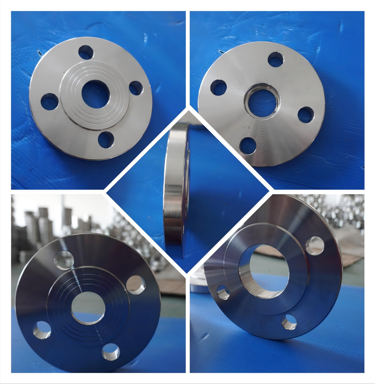
Front, rear and side views show the plate profile, open bore and bolt holes. Dimensions and facing designations must come from the specified drawing.
Pipe OD and flange bore: Resolve the pipe dimensional series and the opening that receives it from their respective specifications.
Bore B1 versus facing B1: Bore diameter B1 is a length; facing B1 is a face designation. Label both clearly when they occur on the same enquiry.
Flange thickness C1: Read the Type 01 thickness column C1. C2 belongs to other flange forms and can give a different value at the same DN and PN.
Pipe wall thickness: EN 1092-1:2018 Annex A, Table A.4 provides a Type 01 pipe-wall basis for non-stainless steels and excludes stainless steels. For stainless pipe, the purchaser specifies nominal wall thickness. PN does not replace that input.
For US pipe, NPS identifies nominal size and schedule identifies a wall-thickness series. Resolve both to the actual OD and wall in the specified pipe standard. Flange Class does not specify pipe schedule.
For a pipe spool or equipment connection, bring together the pipe standard, actual OD, wall thickness, material and flange bore. The project joint detail and qualified welding procedure should identify the required bore clearance, pipe setback and weld size for the intended arrangement. A hubbed slip-on drawing describes a different geometry.
On a US project, establish whether the required connection follows EN/PN, ASME/NPS/Class or an AWWA waterworks specification. An imported valve with an EN connection needs a deliberately specified mating interface; a nominal inch-to-DN label is insufficient to establish that interface.
EN / PN: Specify the EN edition, type, DN, PN, face and complete dimensions for the required interface.
ASME / NPS / Class: Use the specified ASME standard’s own material, rating and dimensional requirements. A matching nominal size is insufficient.
AWWA waterworks: AWWA C207 is a separate steel waterworks flange standard. Use its required class and dimensions where the project specifies it.
ASME’s B16.5 scope covers its own pressure–temperature ratings, materials and dimensions. It limits flange materials to cast or forged products, with plate material permitted for blind flanges and certain reducing flanges. A plate-cut, flow-through EN Type 01 flange therefore cannot be described as a B16.5 slip-on merely because selected dimensions look similar.
A legacy DIN 2573 or DIN 2576 reference requires comparison with the intended EN edition, type, face, drilling, thickness and material. A successor standard or dual-labelled catalogue entry does not establish complete equivalence.
Application qualification remains separate from flange dimensions. NSF describes NSF/ANSI/CAN 61 as a drinking-water contact health-effects standard. For potable-water or fire-protection work, identify the exact product approvals or listings required by the project and check their actual scope; an EN flange designation alone does not establish them.
For an EN connection, MAITO’s EN1092-1 Type 01 plate flange is a relevant product to specify in an enquiry. Include the intended configuration and the mating drawing so the product name does not leave facing, drilling or pipe fit to assumption.
Standard and edition, including any contract-required amendments; Type 01 and quantity.
DN and PN, plus the required material grade and material standard.
Facing designation, face dimensions and required surface finish.
Outside diameter D, bolt circle K, hole count, hole diameter L and drawing orientation.
Flange bore diameter and C1 thickness, with applicable dimensional tolerances.
Pipe standard, actual outside diameter, wall thickness and material.
Design pressure, temperature, fluid and the mating valve or equipment drawing.
Specified gasket and bolting requirements, material documents and any application-specific approvals.
When comparing plate flange options for several standards, separate the enquiry lines by their required connection system. Keep the EN Type 01 item identified by its full designation rather than substituting a DIN, JIS or ASME label under the same general product name.
If the rating basis is unclear or a drawing conflicts with the project specification, obtain the responsible project engineer’s decision before ordering. A supplier’s dimensional confirmation does not replace the project’s design acceptance.
No. Type 01 describes the flange construction, while EN 1092-1:2018 Table 1 permits several manufacturing routes, including forging and manufacture from flat products. Specify the required material and manufacturing route where the project requires them.
No. Material documentation and an application-specific product approval serve different purposes. A material certificate does not, by itself, establish drinking-water health-effects certification, a fire-service listing or acceptance of the complete joint.
A useful flange enquiry joins the component designation to the real pipe and mating connection. Resolve any missing face, drilling or bore detail on those drawings before choosing between offers.
Send MAITO your completed specification and mating-flange drawing to request a quotation for the required Type 01 configuration.


