


close
Choose Your Site
Global
Social Media
Views: 0 Author: Site Editor Publish Time: 2026-11-02 Origin: Site


Choose a rubber lined pipe clamp by matching its assembled clamping range to the pipe’s actual outside diameter, then checking the liner’s documented temperature limits and intended contact condition. The liner should separate the pipe from the clamp’s metal at the designed contact surfaces; unintended hard contact can provide a path for structure-borne vibration.
The clamp also needs tightening instructions and load data for the selected assembly. On heating lines, establish where the pipe must be fixed and where it must move before choosing the support arrangement. A rubber liner alone does not define either function.
Use the outside diameter at the support location, including its permitted variation. DN or an inch designation identifies a pipe size family; it does not fully specify the surface a lined clamp will touch. ISO 6708 defines DN as a nominal-size reference. Use the relevant pipe standard and dimensional data to establish the actual OD and tolerance.
Identify the contact surface. State the pipe material, dimensional standard and size. Identify any paint, coating or support insert that will sit beneath the clamp.
Establish the diameter envelope. Compare the pipe’s specified minimum and maximum OD with measurements at the proposed contact location. Measure in more than one orientation to identify ovality; one reading can miss the largest diameter.
Compare with the lined clamping range. Use the manufacturer’s permitted range for the complete clamp with its specified liner installed. Include applicable coating thickness in the contact diameter without counting it twice.
Check the intended closure. The specified fasteners and liner should achieve the stated fit without modifying the liner or forcing the clamp outside its range. A fit near a range boundary needs particular attention to the full tolerance envelope.
Illustrative fit comparison: suppose a project’s finished contact diameter can vary from 60.1 to 60.8 mm. A documented lined clamping range of 60.0–60.5 mm would not cover that envelope. A range of 60.0–61.0 mm would cover it geometrically, but temperature, loading and movement still need assessment. These are teaching values, not MaitoLead product dimensions.
Do not trim the liner, substitute a thinner strip or add packing to make an unsuitable size close. Those changes alter the contact assembly. Where the clamp surrounds an insulation support insert, identify that insert’s outside diameter and use the specified support detail rather than the bare-pipe OD.
Select the actual liner compound and grade against the temperature history at its contact with the pipe. For an EPDM lined pipe clamp, “EPDM” identifies a polymer family; it does not supply a continuous temperature rating for every compound, profile or finished clamp. The same principle applies to other rubber families and silicone liners.
ISO 11346:2023 relates rubber thermal endurance to changes in selected properties during temperature exposure. Its scope explains why time matters: a short excursion and sustained service are different demands. The standard itself does not give a temperature rating for your clamp.
Temperature information to compare before selecting a liner
Exposure | Project information | Required liner or assembly information |
|---|---|---|
Continuous operation | Expected pipe-surface temperature range and sustained exposure | Permitted continuous range for the identified compound and assembly, with stated conditions |
Peak event | Highest expected contact temperature, event duration and repetition | Permitted peak temperature together with maximum duration, frequency or other restrictions |
Cold operation or shutdown | Lowest contact and ambient temperature, including shutdown conditions | Applicable lower-temperature limit and installation/storage restrictions |
Surrounding exposure | Outdoor conditions, condensation, cleaning chemicals or incidental oil contact | Compatibility information for the actual liner grade and exposed environment |
Use the liner contact temperature as the comparison point. Fluid temperature is an input, but the actual contact condition also depends on the pipe and support detail. If contact temperature has not been established, give the supplier and project engineer the fluid, ambient and insulation conditions rather than assuming a cooler liner.
A sheet headed only “temperature resistance” leaves the continuous-versus-peak distinction unclear. Ask which limit applies to sustained service and what qualifies as a peak. Do not assign an allowable number of hot cycles, extend a peak duration or infer service life from the material name. If the exposure falls outside the documented conditions, select another documented liner/support assembly.
An acoustic bridge forms when a rigid connection bypasses the intended resilient separation. At the pipe interface, a displaced liner or exposed metal edge touching the pipe can create that bypass. Rubber elsewhere around the ring does not remove the hard contact.
ASHRAE’s Noise and Vibration Control guidance describes rigid connections as flanking paths for vibration transmission. Applied to a lined clamp, this means inspecting the installed contact path, rather than judging isolation from the presence of a black strip.
Liner seating and coverage Look for folded, torn or displaced material and exposed clamp metal at the pipe-contact surfaces, including near the split and closing lugs.
Compression and closure Compare the seated liner and clamp closure with the installation instructions. Extruded material or metal touching the pipe needs investigation; tighter closure is not an acoustic improvement criterion.
Other hard contact Check whether the pipe touches adjacent channel, bracket edges or another rigid part outside the lined contact. Treat any required isolation farther along the support path as a separate assembly detail.
Bolts joining the clamp halves normally connect metal parts by design. That alone is not proof of an acoustic bridge across the pipe-to-clamp liner. Follow the actual path: does an unintended rigid connection bypass the resilient separation?
This inspection can identify contact defects; it cannot quantify room noise reduction. A numerical acoustic claim needs a test report for the relevant assembly, loading and mounting conditions. Do not infer a decibel reduction from rubber thickness, colour or an unrelated clamp test.
Use tightening instructions and allowable-load data that identify the same clamp size, liner and fastener configuration. Closing the bolts establishes a mechanical contact condition; it is not a separate way to choose an acoustic or sliding function.
Installation instruction Obtain the prescribed tightening method, any stated torque, closure condition or gap, bolt sequence and inspection requirements for the selected version.
Supplied hardware Identify bolt, nut, connection thread and any specified washers or spacers. Do not assume replacement hardware gives the same assembly performance.
Allowable load Request the usable load, force direction, units, mounting orientation and conditions. Distinguish an allowable service load from a failure or proof-test load.
Temperature and contact limits Check whether the load information applies with the selected liner, pipe surface and operating temperature, including any stated reductions or restrictions.
Over-tightening can change liner compression and contact geometry. Under-tightening can leave an assembly unable to perform its intended mechanical function. Where the maker provides no tightening value, obtain the correct instruction rather than borrowing a torque from another clamp or choosing one from bolt diameter alone.
The engineer must also compare the complete support arrangement with the project reactions. Pipe and contents weight, insulation and applicable operating or movement forces can matter. ASME’s discussion of pipe forces explains why transient forces can affect support selection. A clamp load table does not establish the capacity of the rod, channel, connection and structural attachment around it.
Keep these checks within the specified project system. This selection guide provides no universal support spacing, anchor resistance or design load.
A fixed point restrains the pipe’s intended axial movement at a defined location. A sliding point carries its specified loads while allowing defined travel. Assign those functions from the pipe movement design before selecting the clamp and its accessories.
Fixed and sliding support functions on a heating line
Selection question | Fixed point | Sliding or guided point |
|---|---|---|
What happens to axial movement? | Movement is restrained by the designed fixed-point assembly | Movement is permitted in the specified direction and travel range |
What must the assembly documentation establish? | Restraint capacity and the load path into the structure | Permitted travel, guidance, loading and any stated friction conditions |
Where does relative movement occur? | The restrained interface is intended to remain fixed | At the specified pipe/liner interface or a separate sliding accessory |
What does a rubber liner prove? | Liner presence alone does not establish anchor capacity | Liner presence alone does not establish reliable sliding |
One arrangement may grip the pipe in the lined clamp and accommodate travel in a separate sliding attachment. Another may permit the pipe to move through a specifically designed clamp contact. Identify which interface moves; a low-friction description during positioning does not necessarily establish permitted movement throughout service.
Do not create a sliding support by arbitrarily loosening an ordinary clamp. Use the manufacturer’s specified configuration, including any required spacers or travel components. Ask the engineer to define movement direction, expected travel and restraint locations; ask the supplier which assembly can perform that function. This distinction addresses thermal movement, not seismic restraint or vertical riser support design.
A useful enquiry describes the pipe-contact conditions before naming a quantity. Include the following information so the proposed size and liner can be compared with the same project requirements.
Pipe and contact diameter Pipe material and standard, nominal designation, minimum/maximum OD, measured ovality and any coating or support insert beneath the clamp.
Thermal exposure Continuous contact-temperature range, peak temperature, peak duration and frequency, lowest shutdown temperature and relevant environmental exposure.
Mechanical function Support orientation, project load reactions and directions, plus whether the point is fixed, sliding or guided and the required travel.
Requested product information Exact clamp size/identifier, liner compound and grade, permitted lined clamping range, installation instructions, applicable load table and relevant test or certification scope.
MaitoLead’s rubber lined pipe clamp is listed with a galvanized carbon-steel body and a nominal catalogue range of 1/2 inch through 8 inch. Use that range to identify a product family, then request the actual OD range, liner grade and assembly data for the required size.
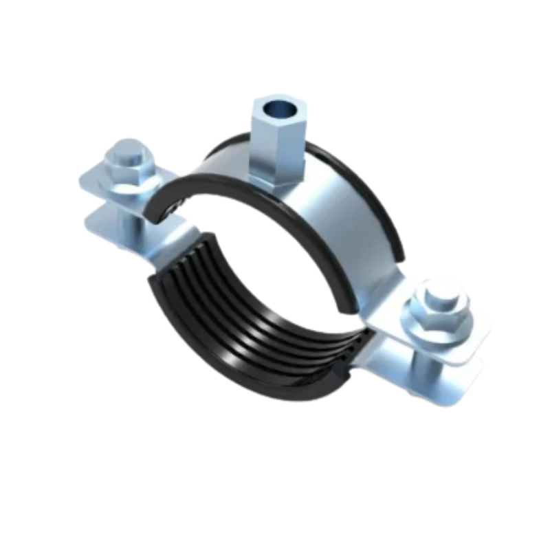
MaitoLead split clamp showing the ribbed liner, closing bolts and threaded connection boss.
For a package containing several support functions, compare the clamp and hanger options against each location’s assigned job rather than treating every listed fitting as interchangeable.
No. A support liner normally contacts the pipe exterior, while NSF/ANSI/CAN 61 addresses health effects for drinking-water-contact materials and components. A drinking-water application title does not establish a certificate for the liner; verify the exact scope if the project requires one.
No. The clamp supports the outside of a pipe; its liner does not seal the conveyed fluid or provide a line-pressure rating. A flexible rubber joint is a separate pipeline connection with its own pressure, movement and installation requirements.
Use it only where the project specification and applicable market requirements accept the exact component and configuration. Acoustic lining does not establish fire-system listing or seismic-restraint suitability; verify any required listing against the identified product and supporting documentation.
Do not assume so. An insulation support must address load distribution and vapor-retarder continuity as well as fit. The National Insulation Association’s installation guidance explains those support-interface concerns; select the specified insulation insert or shield rather than treating a thin acoustic liner as equivalent.
Choose a candidate only when its documented contact range, thermal exposure limits and mechanical function match the project. If a parameter is unclear, identify that parameter in the enquiry so the proposed assembly can be assessed against it.
Send MaitoLead your pipe OD envelope, temperature cycle, support loads and fixed or sliding requirements, and request the matching size-specific clamp information.


