


close
Choose Your Site
Global
Social Media
Views: 0 Author: Site Editor Publish Time: 2026-11-03 Origin: Site


An eccentric grooved drain cap is a candidate when a horizontal pipe end needs a lower drain entrance. A concentric outlet suits a connection on the pipe axis. The useful comparison is the installed opening height and the space needed by the connected drain, rather than the hole position alone.
For either form, pipe fall, the cap’s internal shape and the downstream drain route determine where water can remain. A lower outlet can help the local path without guaranteeing that the whole system empties.
A concentric hole lies on the main pipe axis. An eccentric hole is offset from it. On a horizontal pipe end, that offset can place the outlet closer to the bottom, provided the selected cap permits the intended orientation. Compare the lower inside edge of the opening, often called its invert, rather than only its center.
Concentric and eccentric outlets: compare the installed geometry
Selection point | Concentric outlet | Eccentric outlet |
|---|---|---|
Opening position | Centered on the pipe axis. | Offset from the pipe axis. |
Effect of rotating the cap on a horizontal pipe end | The opening stays centered; rotation does not lower it. | The opening moves toward the bottom, side or top as its angular position changes. |
Drain entrance on a horizontal run | A smaller centered opening can leave water below its lower edge. | An opening positioned below the axis can provide a lower entrance; the actual offset and internal shape determine how low. |
Downward-facing end of a vertical pipe | The outlet points through the bottom face on the pipe axis. | The outlet is displaced across the bottom face. Rotation does not provide the same lowering effect as on a horizontal pipe end. |
Space near a floor or wall | The centered connection may suit an on-axis valve or drain route. | A lower or sideways port changes valve and tool clearance. A lower entrance can bring the valve closer to an obstruction. |
An eccentric hole helps only the part of the drainage path that its lower position actually improves. A pipe falling away from the cap, a recess inside the body or a drain connection that rises again can still retain water. Trace the proposed arrangement on the section and elevation drawings.
Trace the main pipe to the terminal end. Compare its internal low points and fall with the cap location. Water in a lower pocket elsewhere may have no gravity path to this opening.
Trace the inside of the cap into the port. Locate the opening’s lower edge and any internal lip or recess. An externally low boss does not show the entire internal passage.
Trace the connecting pipe and valve to the discharge destination. Include elbows, rises and the valve passage. The destination and any backpressure also belong in the drainage design.
For a downward-facing vertical end, assess the bottom face and its passage into the outlet. Moving the hole across that face can help the connected layout, but it does not automatically change the lowest drainable level. The project design also needs an appropriate air path as liquid leaves.
Specify the main grooved connection and the small threaded outlet separately. The cap’s main nominal size identifies the pipe end it closes; it does not identify the drain thread. Compare the actual main pipe outside diameter and connection profile, then the outlet’s nominal size, full thread designation and mating part. Concentric and eccentric describe hole position; neither name specifies the outlet size or thread family.
NPT. ASME B1.20.1 covers NPT and other inch pipe-thread forms. A nominal inch size alone is not a complete connection description.
ISO 7-1. This standard concerns pipe-thread joints that make their pressure-tight seal at the threads. The full internal and external thread designations still matter.
ISO 228-1. This standard covers parallel fastening threads; pressure-tightness is provided elsewhere in the designed joint. The mating component needs the intended sealing arrangement.
A generic “BSP” description leaves important details unresolved. Likewise, seeing a parallel female thread does not by itself identify ISO 228-1: ISO 7-1 also includes parallel internal forms. Match the documented thread pair and sealing method instead of treating similar-looking connections as interchangeable.
A valve with a compatible male inlet may connect directly if both component instructions permit it. A valve with a female inlet usually needs a compatible male-ended nipple or adaptor to meet a female cap outlet. A nipple can move the valve farther from the cap face and improve access, but it adds length and another joint. Include the valve’s outlet connection and discharge route in the same layout; matching its inlet thread alone does not settle the arrangement.
A lower outlet is useful only if the connected drain remains accessible. In an illustrative floor-level layout, an offset port may lower the drain entrance while bringing the valve body or wrench too close to the floor. Moving the port sideways changes that clearance, but also changes its entrance height.
Coupling tools. Allow the specified socket or wrench to reach the coupling hardware, including its approach direction.
Threaded-joint tools. Allow room for the tools and counterholding surfaces required by the connecting-part instructions.
Valve operation. Show the full handle or handwheel travel, rather than only the valve body at one position.
Removal and maintenance. Show how the valve, nipple and cap can be withdrawn with nearby walls, insulation and services in place.
Use the actual component dimensions and tool requirements to establish these spaces; there is no single clearance for every drain cap. HSE’s HSG253 process-isolation guidance discusses accessible discharge points and warns that blocked drains or a gauge reading alone can give misleading indications of depressurisation. Cap, plug or coupling removal belongs under the site’s isolation procedure and competent verification, rather than being inferred from an apparent lack of flow.
MaitoLead’s Cap with Concentric Hole provides a central opening for an on-axis outlet layout. Compare that position with the intended valve and drain route when a centered connection suits the pipe termination.
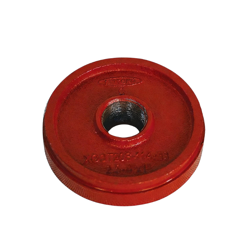
Central threaded opening in MaitoLead’s concentric-hole cap.
Its Cap with Eccentric Hole provides an offset opening. Compare this option when the terminal drain needs a different entrance position, using the intended cap orientation and connected valve space together.
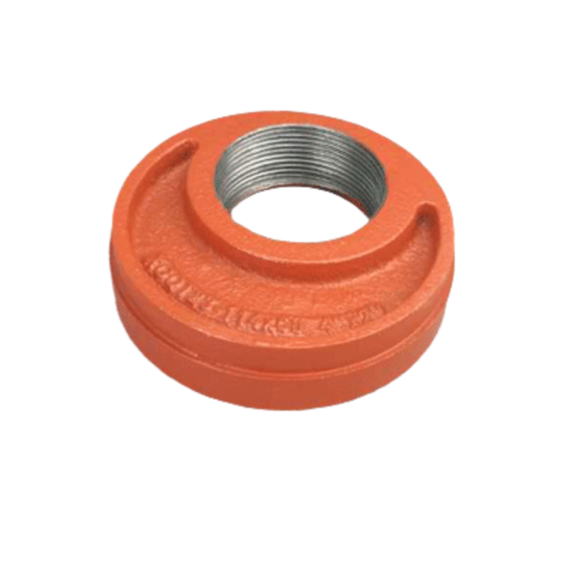
Offset threaded opening in MaitoLead’s eccentric-hole cap.
Cap body. Request the exact item and drawing revision, main size and mating outside diameter, connection profile, outlet location and internal passage, outlet size and thread designation, material and finish, service ratings, and cap-specific installation instructions.
Matching coupling. Identify the exact coupling model and size, permitted cap and pipe combination, supplied gasket for the service, applicable pressure and temperature limits, and that model’s assembly instructions. A generic grooved connection description does not identify the coupling.
Main pipe and connecting nipple. State the main pipe’s dimensional/material specification and prepared end profile. For the smaller nipple or connecting pipe, specify both end connections, full male thread designations where applicable, length, material, service limits and connection instructions.
Drain valve. Identify the valve model, inlet and outlet connections, fluid and temperature suitability, pressure limits, installation instructions, operating travel and maintenance-removal dimensions.
Apply ratings to the specified component combination and service conditions. Where certification is required, compare the exact model, size and conditions with the applicable listing. UL Product iQ and the FM Approval Guide provide official lookup routes for their respective certifications; a general supplier logo does not identify the accepted configuration.
No. A hose tail or adaptor can have different connections at its two ends. Specify the cap-to-adaptor thread separately from the hose-side connection, including the intended sealing arrangement.
A low drain opening does not by itself provide a path for air trapped at higher points. Vent locations and the air path needed during drainage belong in the system layout; the cap’s label does not establish that function.
No. A plug closes the opening; a suitable valve provides a controlled connection to the drain route. The intended function and site maintenance procedure determine the arrangement. A removable plug alone is not a reason to assume the opening can be used while the system is pressurized.
Only where there is a suitable continuous path to it. A separate low pocket or isolated pipe section may need another drainage provision defined by the project design.
Carry the chosen port position into the full drain layout before ordering. The cap, coupling, connecting pipe and valve references should describe the same arrangement, including the space needed to use and maintain it.
Send MaitoLead your main pipe size and outside diameter, required outlet thread, intended outlet position, valve arrangement and service conditions. Request the corresponding cap drawing and matching coupling and connecting-part documents.


